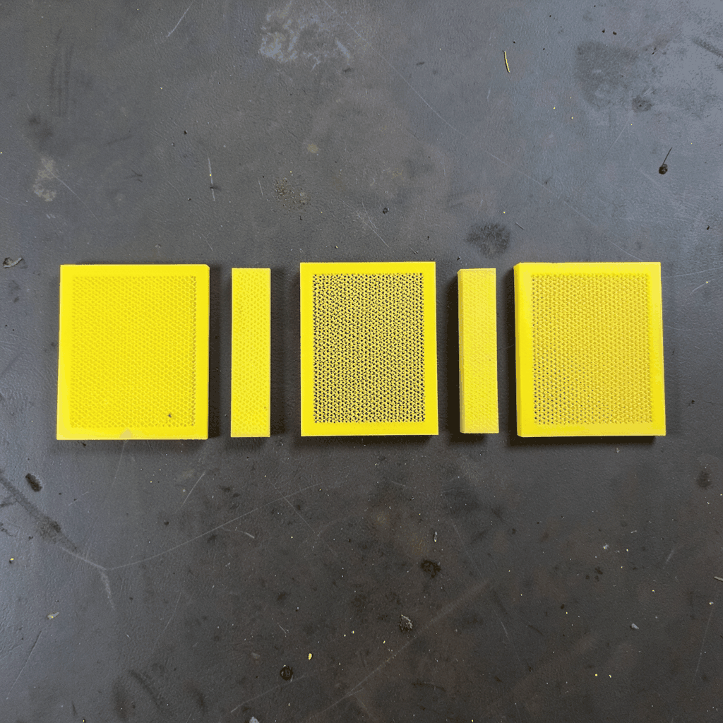
Custom wire mesh trays for PCB soldering and reflow ovens
Printed circuit board production depends on controlled handling at every stage, from component placement to soldering, inspection, and final testing. A suitable mesh tray supports the board during heating, allows air circulation, and helps operators move assemblies safely between processes. When the tray is poorly matched to the board or oven, it can cause distortion, uneven heating, solder contamination, and unnecessary production delays.
Custom wire mesh trays are useful for Australian electronics manufacturers, contract assemblers, repair centres, and industrial workshops that handle different PCB sizes or unusual assemblies. They can be designed around conveyor widths, reflow profiles, soldering fixtures, washing systems, and manual handling requirements rather than forcing a standard basket to fit an existing process.
The right tray is a combination of material selection, mesh geometry, structural support, and practical handling. A manufacturer experienced in stainless steel and alloy fabrication can produce a carrier that performs in high-temperature environments while remaining easy to clean, stack, identify, and replace.
Why mesh trays suit PCB soldering processes
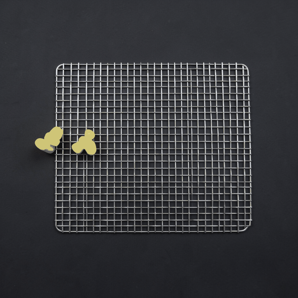
A wire mesh tray holds a printed circuit board above a supporting surface while leaving open areas beneath and around it. This structure allows heated air to circulate through the assembly during reflow soldering and reduces the risk of large solid surfaces creating uneven thermal conditions. Open mesh can also assist with drainage during aqueous cleaning or solvent-based process stages, where permitted by the production specification.
The tray can be used as a transport carrier between screen printing, pick-and-place, reflow, inspection, and repair. It may also support boards during wave soldering, preheating, curing, or storage. For small assemblies, the mesh prevents components from falling through while keeping the overall carrier light enough for manual movement.
A well-designed carrier should hold the PCB securely without covering solder joints, test points, fiducial marks, or heat-sensitive components. Contact points are often placed along the board edge or in defined non-functional areas. This approach reduces shadowing and gives operators consistent access to the assembly throughout the production cycle.
Materials for high-temperature and clean handling
Stainless steel is a common choice for PCB soldering trays because it combines strength, corrosion resistance, and relatively stable performance during repeated heating. Grade 304 is suitable for many general-purpose electronics applications, while 316 stainless steel may be preferred where cleaning chemicals, humidity, or coastal exposure create a more demanding environment. Australian facilities near Brisbane, Sydney, or other coastal locations may benefit from additional attention to corrosion protection and storage conditions.
The selected alloy should reflect the complete process rather than the peak oven temperature alone. Lead-free reflow commonly reaches approximately 235–260°C, while certain specialised processes may impose higher or more frequent thermal loads. Stainless steel, heat-resistant steel, aluminium, copper, or other alloys can be considered according to temperature, weight, electrical requirements, and chemical exposure. Aluminium is lightweight, although its thermal expansion and surface characteristics must be assessed carefully.
Flux residues, solder splashes, cleaning agents, and repeated thermal cycling can affect mesh life. A tray supplier should review the process profile, cleaning method, expected loading, and service temperature before recommending a material. Smooth welds, clean edges, and suitable surface finishing help prevent residue accumulation and protect operators from sharp points.
Mesh geometry and tray construction
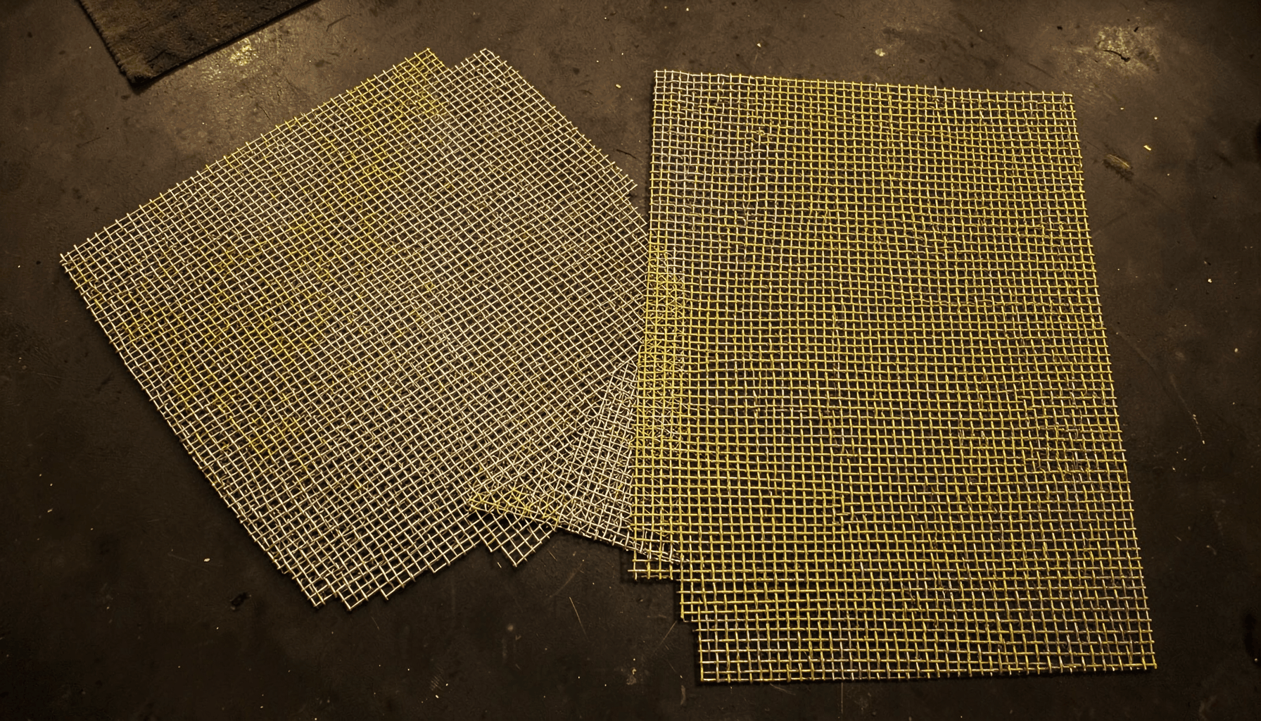
Mesh aperture determines how well the tray supports the board and how freely heat and cleaning fluids can pass through it. Fine mesh is useful for small or lightweight components, while a larger opening can improve airflow and reduce tray weight. Wire diameter must be balanced with stiffness: wire that is too thin may deform under repeated loading, while heavy wire can create unnecessary thermal mass or interfere with component clearance.
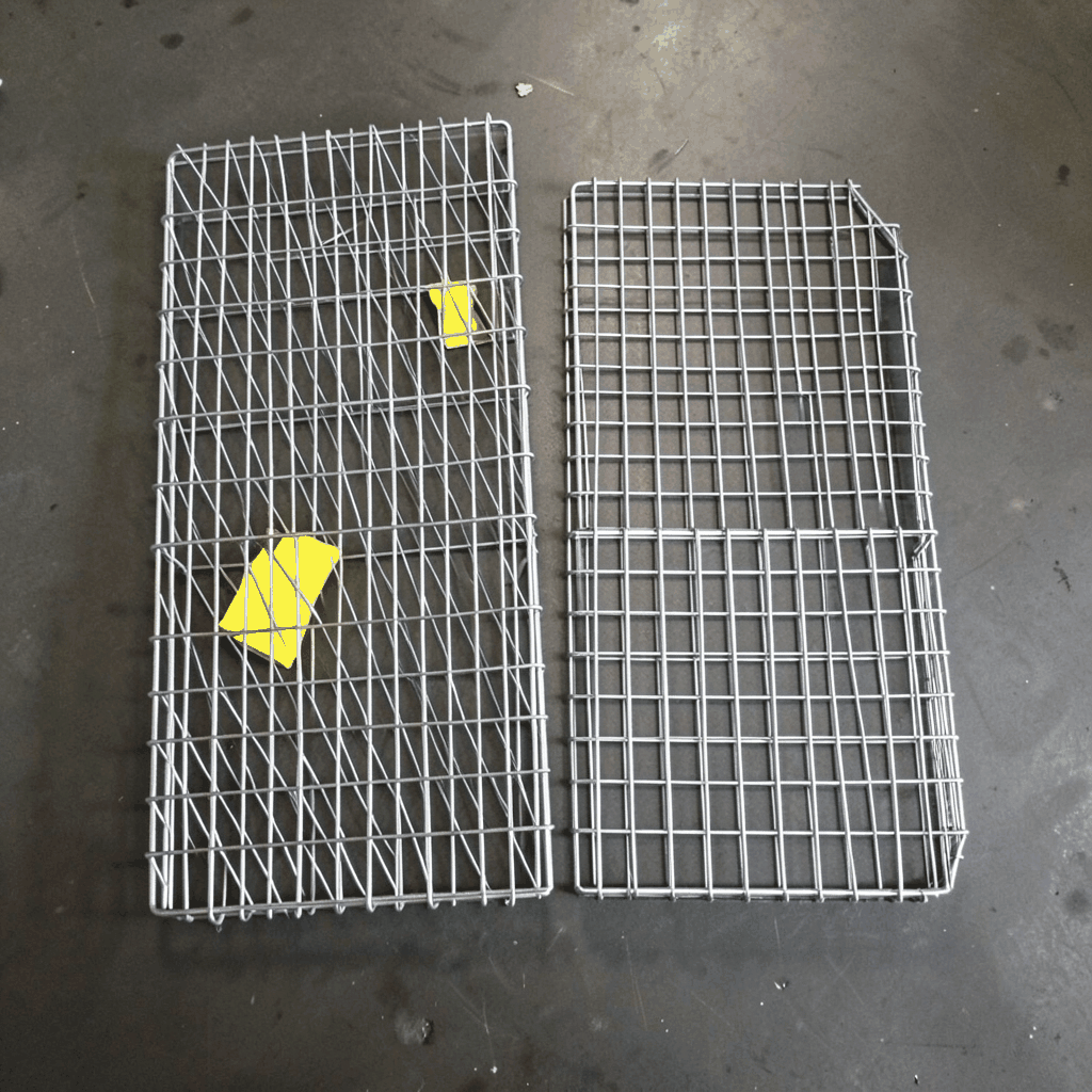
The tray perimeter may include a welded frame, folded edge, reinforced rim, or formed sidewall. These features improve rigidity and make the carrier easier to lift. Handles can be added to opposite sides, and stacking feet can maintain a stable gap between trays during storage or oven loading. For automated equipment, the tray may require precise external dimensions, guide rails, locating holes, or registration points.
Custom supports can include pins, clips, spring fingers, adjustable stops, corner retainers, and removable inserts. These details are especially valuable when one carrier must accommodate several board variants. However, adjustable features should be designed so they cannot loosen during vibration or obstruct components. The cleanest design normally uses the fewest contact points needed to restrain the PCB.
Dimensional accuracy is critical when trays move through a conveyorized reflow oven. A small amount of warping can cause contact with guide rails or loading mechanisms. The manufacturing drawing should define length, width, height, flatness, wire diameter, aperture size, weld locations, and permitted tolerances. A trial sample can then be tested with the actual PCB and oven before a larger production run.
Designing for Australian production environments
Australian electronics production ranges from specialised contract assembly in Melbourne and Sydney to industrial control, medical, communications, renewable-energy, and mining-related equipment manufactured in Adelaide, Perth, and regional centres. These operations often handle short and medium production runs, frequent product changes, or boards with unusual shapes. A custom tray can reduce changeover time when standard international carriers do not match local equipment.
Climate and logistics also influence tray selection. Brisbane and northern sites may experience high humidity, while coastal workshops face salt-laden air and storage conditions that accelerate corrosion. A facility in Perth or a regional industrial area may need trays that can be stacked efficiently and shipped over long distances without bending. Compact nesting, durable packaging, and clear identification can lower freight damage and simplify inventory control.
Australian businesses also need to account for import timing, GST, local warehousing, and the cost of replacing a tray that does not meet the stated dimensions. A detailed specification and pre-production sample can prevent expensive delays. If the carrier will be used with machinery, the design should be reviewed against the equipment supplier’s loading instructions and relevant workplace safety expectations.
For facilities supplying mining, transport, infrastructure, or other regulated industries, traceability may be important. Material certificates, inspection records, batch identification, and dimensional reports can support internal quality systems. The exact documentation should be agreed before manufacture, particularly when the tray becomes part of a validated soldering or cleaning process.
Practical features for loading, cleaning, and storage
Operators should be able to load a PCB quickly without catching cables, component leads, or protective gloves on the tray. Rounded corners, formed handles, and deburred edges improve everyday safety. A contrasting identification mark, engraved code, or durable tag can help distinguish trays assigned to different board families or reflow programs.
Cleaning requirements should be considered at the design stage. Narrow gaps, enclosed hollow sections, and poorly finished welds can trap flux and cleaning residue. Open construction, accessible surfaces, and consistent weld quality make inspection easier. If the trays are washed regularly, the selected material and finish should be compatible with the cleaning chemistry and water quality used at the site.
Storage is another overlooked issue. Nestable tray profiles reduce shelf space, while stackable versions can protect components from contact with the carrier above. A tray intended for automated loading may need a very different base and sidewall arrangement from one used only for manual transport. The supplier should know whether the tray will be carried by operators, placed on carts, loaded by a conveyor, or handled by a robotic system.
Workshop staff may also need durable tools for trimming wire, preparing fixtures, or maintaining adjacent production equipment. General maintenance resources such as industrial tools can support this work, although the tray itself should be engineered so routine handling does not depend on improvised modifications.
Quality checks before production release
A prototype tray should be checked with the real PCB, including the tallest components, connectors, heatsinks, sockets, and underside features. The assembly should sit firmly without excessive pressure, and there should be adequate clearance from the mesh, retaining points, oven rails, and any top-mounted heating elements. A simple fit test often identifies problems that are not obvious from a two-dimensional drawing.
Thermal testing can compare board temperature, tray temperature, and conveyor movement through the intended reflow profile. The carrier should remain sufficiently flat after repeated heating cycles, and its contact points should not create visible solder defects or obstruct inspection. For critical assemblies, test runs should include the heaviest expected PCB and the longest anticipated operating cycle.
Inspection should cover aperture size, frame dimensions, weld integrity, flatness, edge finishing, and the operation of clips or removable supports. Any coating or surface treatment should be verified for temperature suitability and possible contamination. Stainless steel trays are often left in a clean natural finish, but the final choice depends on handling, corrosion exposure, and process cleanliness.
A clear drawing and acceptance standard make repeat orders more consistent. The specification can record the PCB reference, tray revision, material grade, wire size, mesh opening, overall dimensions, support locations, and permitted tolerances. This documentation is valuable when production moves between shifts, lines, or facilities, and it gives Australian buyers a reliable basis for communicating with an overseas manufacturer.
Custom mesh solutions for evolving PCB lines
The best tray design supports the complete workflow rather than a single oven pass. A carrier may need to move from printing to placement, reflow, inspection, testing, and packing without transferring the PCB repeatedly. Reducing manual handling can lower the risk of knocked components, contamination, and operator errors, especially during small-batch production with frequent product changes.
Customisation can also accommodate depanelised boards, odd-shaped assemblies, edge connectors, flexible sections, or panels containing multiple circuits. Different mesh densities, reinforcement patterns, retaining methods, and frame profiles can be combined to suit the application. For a growing electronics business, interchangeable inserts may provide a practical way to use one base frame across several PCB designs.
Shuo Ke Wire Mesh Product Technology Co., Ltd. can develop fabricated mesh carriers using stainless steel, aluminium, iron, copper, and other alloys according to the required process. Its broader metalworking capability supports custom baskets, filters, guards, panels, and industrial mesh components, which can be useful when a production line requires related handling or protection products.
A clear enquiry should include board dimensions, component height, weight, process temperature, oven opening, conveyor width, cleaning method, loading direction, expected quantity, and any required documentation. Photos, sketches, and a sample PCB can further reduce uncertainty. With these details, the manufacturer can recommend a suitable construction and produce a tray that is practical for the Australian operating environment.
Send the PCB dimensions and process requirements to Shuo Ke Wire Mesh Product Technology Co., Ltd. to begin a design review for a durable soldering or reflow carrier. A properly specified mesh tray can improve board handling, protect production equipment, and provide repeatable support across the life of the assembly process.