Fabricating Custom Mesh Trays for Automated Pick-and-Place Assembly Lines
Automated pick-and-place equipment depends on consistent part presentation. Components must arrive in a predictable position, with enough separation for robotic grippers, vacuum heads, or vision-guided tools to identify and collect them. Custom mesh trays support this requirement by combining controlled geometry, open airflow, drainage, visibility, and mechanical strength in one reusable handling solution.
Unlike standard solid bins, perforated and woven metal trays can be designed around the dimensions and movement pattern of a particular assembly line. The tray may include locating pockets, dividers, sloped surfaces, reinforced edges, or mounting points for conveyors and transfer fixtures. These details help reduce jams and improve repeatability from loading through final placement.
Shuo Ke Wire Mesh Product Technology Co., Ltd. manufactures and processes stainless steel, aluminum, copper, iron, and alloy mesh products for industrial and architectural use. Its fabrication experience can be applied to material-handling components that require durable construction, accurate processing, and a practical balance between function and appearance.
Starting With Part And Process Requirements
The best tray design begins with the component rather than the mesh. Engineers need to understand the part’s length, width, height, weight, center of gravity, surface sensitivity, and allowable contact areas. A tray for stamped metal pieces will have different requirements from one handling molded plastic housings, electronic components, fasteners, or machined parts.
The production sequence also affects the design. A tray may travel through a conveyor, robotic cell, washing station, drying area, inspection point, or storage rack before returning to the loading position. Each stage creates different demands for stiffness, cleanliness, drainage, heat resistance, and access. Defining the full route prevents a tray that works at the pick point but interferes with upstream or downstream equipment.
Loading orientation deserves early attention. Some products can lie flat, while others must remain upright or maintain a specific face toward a camera. Dividers, guide rails, and formed pockets can control orientation, while a mesh base prevents small debris or liquid from collecting around the components. For delicate parts, contact surfaces should be smooth, rounded, and limited to approved areas.
Selecting Mesh, Metal, And Opening Size
Metal choice affects weight, corrosion resistance, rigidity, thermal performance, and cost. Stainless steel is widely used where trays must resist moisture, cleaning chemicals, abrasion, or repeated industrial handling. Aluminum offers lower weight and can reduce the load on conveyors and robotic tooling. Copper and specialty alloys may be selected for conductivity or particular environmental conditions, while iron-based materials can provide economical strength when corrosion protection is properly specified.
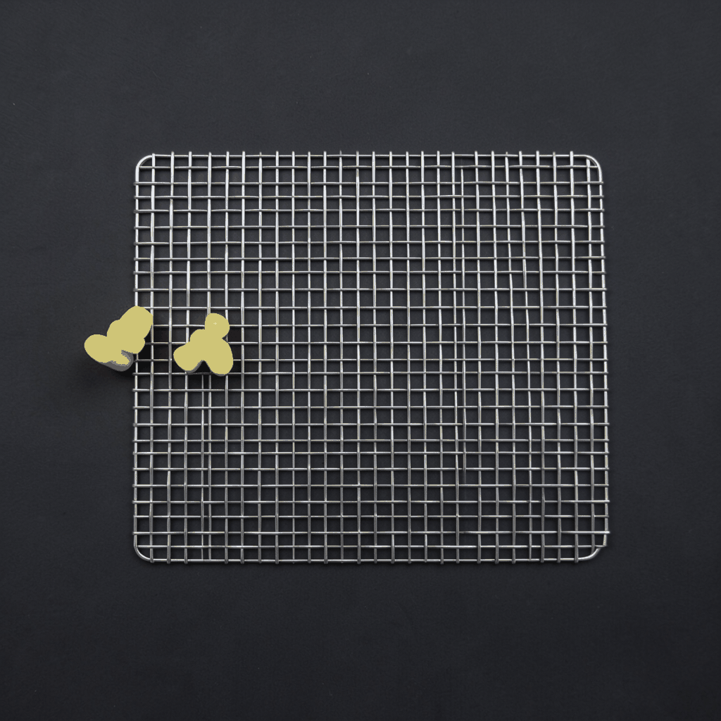
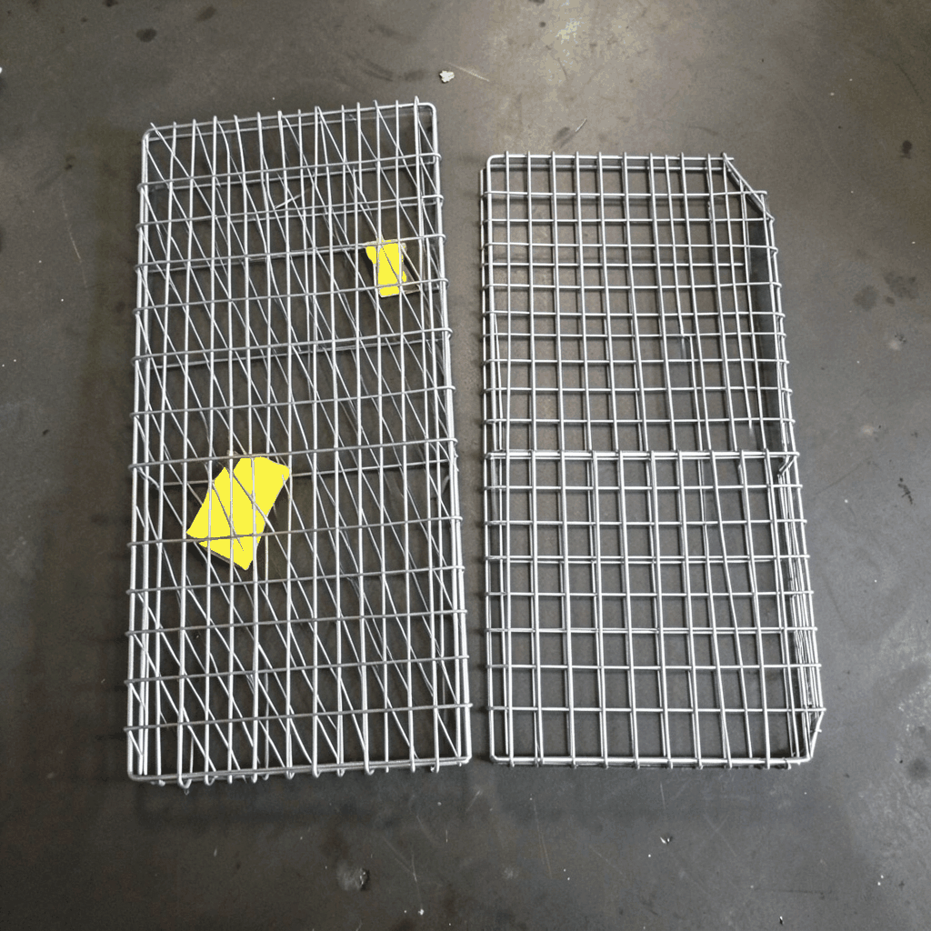
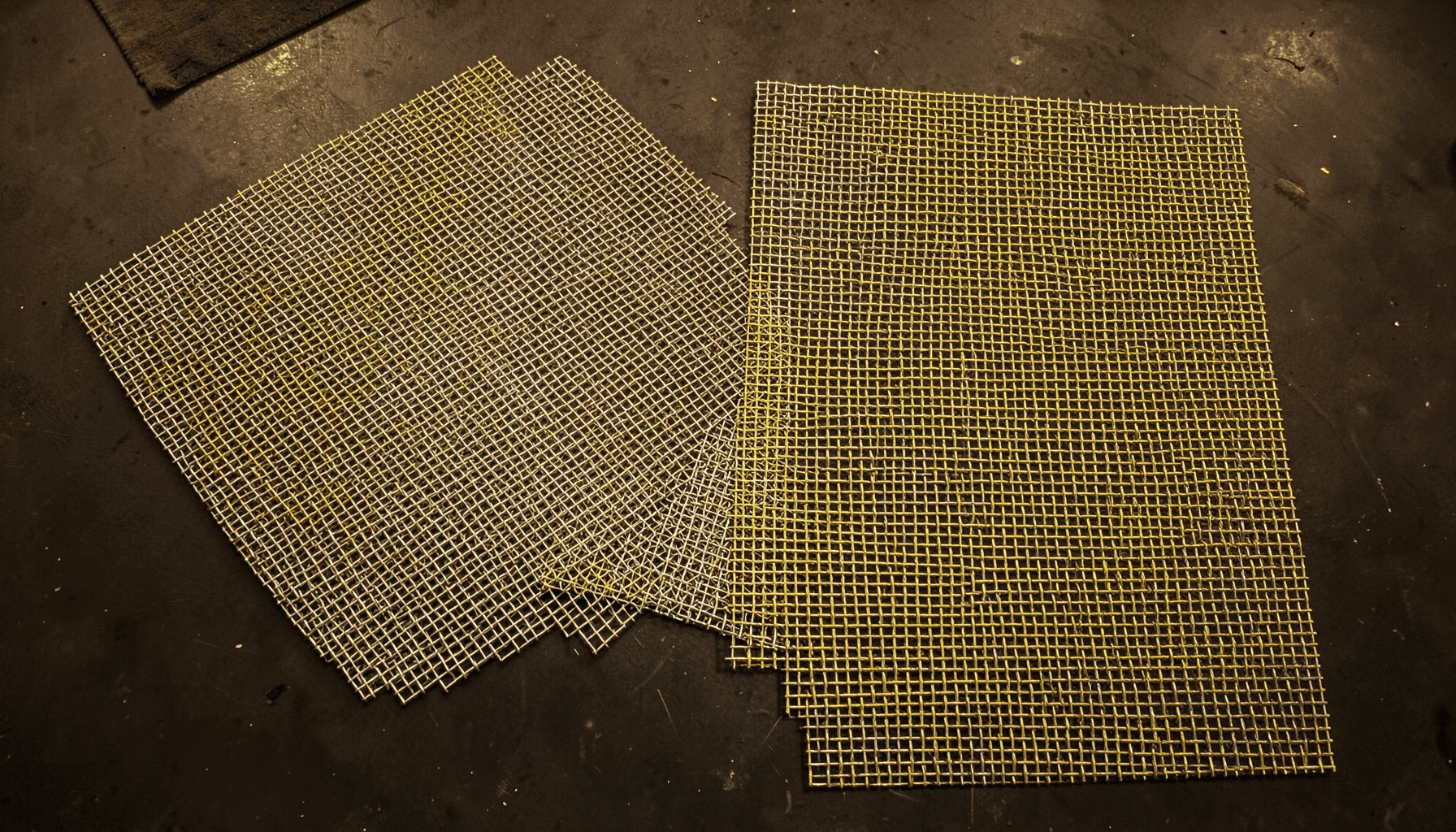
Mesh style is equally important. Woven wire mesh offers a broad range of openings and can provide a compliant contact surface for certain parts. Welded wire mesh gives a more rigid structure with stable intersections, making it suitable for trays that must retain their shape during repeated transfers. Expanded metal can combine ventilation, drainage, and efficient material use, while perforated sheet provides controlled openings and a clean, uniform appearance.
Opening size should be based on the smallest component feature that must be supported, the largest contaminant that should pass through, and the reach of the pick tool. Openings that are too large may allow parts to tilt, snag, or fall through. Openings that are too small can reduce drainage and airflow while adding unnecessary material. A suitable design often uses a finer mesh in contact zones and a more open structure in non-contact areas.
Designing For Repeatable Robotic Handling
A custom tray must present components consistently enough for the automation system to work within its programmed tolerance. This may require pockets with fixed pitch, registration holes, chamfered entry points, or a datum edge that aligns with a conveyor stop. The tray should also include a clear reference feature that sensors can detect without confusing it with the product.
Robotic access determines the height and spacing of internal features. Dividers need to prevent parts from shifting without blocking the gripper or vacuum cup. Excessively tall walls can obstruct cameras and create shadowing, while low walls may fail to contain components during acceleration. When a tray carries multiple pieces, pitch and clearance should account for both product variation and tool approach angles.
The base should be stiff enough to avoid deflection when loaded. A flexible tray can change the height of a component relative to the robot, producing missed picks or inconsistent placement. Reinforcing ribs, folded edges, perimeter frames, and formed flanges can increase rigidity without making the complete unit excessively heavy. These features also provide useful locations for handles, stacking guides, or conveyor supports.
Mesh products used in public and architectural environments demonstrate how perforated surfaces can combine structure with visual control. For example, integrated seating panels show how carefully processed metal mesh can be incorporated into a functional assembly while retaining a clean, durable finish. Industrial trays use the same broader principle: the opening pattern and supporting frame should be designed as one engineered unit.
Choosing A Construction That Fits The Cell
The fabrication method should reflect the tray’s load, geometry, cleaning requirements, and expected service life. A simple flat mesh panel with a formed perimeter may be sufficient for lightweight parts. Heavier loads or frequent impacts may call for welded frames, folded sheet sections, cross supports, or thicker wire. Where trays must stack, nesting geometry can be added to limit storage volume without allowing one tray to crush the parts below it.
The following comparison helps identify a suitable construction direction before detailed drawings are prepared.
| Construction approach | Useful characteristics | Typical considerations |
|---|---|---|
| Welded wire mesh tray | Rigid intersections, stable shape, good airflow | Weld quality, exposed joints, and corner finishing require control |
| Woven wire mesh tray | Flexible opening selection, smooth continuous wire surface | May need a reinforcing frame for heavy or impact-prone loads |
| Perforated sheet tray | Consistent openings, clean appearance, strong formed edges | Less open area and potentially higher weight than wire mesh |
| Expanded metal tray | Strong-to-weight performance, drainage, ventilation | Pattern direction and edge treatment affect part support |
| Hybrid mesh and sheet tray | Combines precise pockets with open support areas | More fabrication steps and closer tolerance coordination |
For automated assembly, hybrid designs are often valuable. A perforated or solid sheet insert can create a stable datum or component pocket, while mesh sections reduce weight and allow air, liquid, and debris to pass through. The frame may use folded stainless steel or aluminum profiles, with welded or mechanically fixed joints selected according to maintenance and cleaning practices.
Stacking and transport features should be tested with the loaded weight, not an empty tray. If trays are nested, the nesting stops must keep internal dividers from contacting the components. If they are stacked, the upper tray should transfer force through its frame rather than through the products. Handles, lifting points, and forklift access can be included when the same tray moves between manual and automated areas.
Controlling Fabrication Accuracy And Surface Quality
Accurate fabrication starts with a drawing that identifies mesh type, wire diameter or sheet thickness, opening dimensions, overall tolerance, bend locations, weld requirements, and critical datums. Vague descriptions such as “heavy-duty mesh” can lead to inconsistent results because strength and opening size depend on several variables. A production-ready specification should distinguish functional dimensions from cosmetic ones.
Cutting methods must be selected according to the metal and geometry. Laser cutting is suitable for precise sheet profiles, slots, registration holes, and small batches of customized parts. Punching can be efficient for repeated perforation patterns, while shearing and forming support high-volume sheet fabrication. Wire mesh may require controlled cutting, welding, edging, and frame assembly to prevent distortion.
Edges are especially important in a tray that is handled frequently or placed near sensitive components. Cut wire ends should be welded, folded, capped, or otherwise protected. Sheet edges can be hemmed or formed into flanges. Weld beads should be continuous where leakage or cleanliness matters, while intermittent welding may reduce heat distortion in non-sealed structures. Any finishing operation must preserve the opening size and avoid creating burrs that could damage products.
Surface treatment depends on the operating environment. Stainless steel may be supplied with a clean mill finish or treated to improve corrosion resistance and appearance. Aluminum can be anodized or coated when additional protection is needed. Iron and carbon steel may require powder coating, plating, or another corrosion-control system. The selected finish should be compatible with detergents, lubricants, heat, and contact with the handled components.
Testing The Tray In Real Operating Conditions
A prototype should be tested with production parts, production tooling, and representative line speeds. Static loading alone does not reveal how components behave during conveyor starts, stops, transfers, vibration, or robotic access. A short trial can identify snagging points, unstable orientations, blocked camera views, and interference with clamps or guide rails.
Pick reliability is influenced by more than pocket dimensions. The tray must maintain its position relative to the robot, and the product must remain within the expected pickup window. Tests should measure successful picks, mispicks, double picks, dropped parts, and recovery time. If vision is used, inspect glare, shadows, contrast, and the visibility of fiducial or registration features.
Cleaning and maintenance trials are also valuable. Mesh openings should allow debris and fluids to leave the tray rather than collect in corners. Welded areas, folded seams, and enclosed profiles need inspection if contamination could affect the product. The design should permit quick visual checks and replacement of damaged components. If a tray is part of a closed-loop system, its identification mark or barcode should remain readable after washing and repeated handling.
Durability testing can include repeated stacking, impact simulation, loaded conveyor cycles, and exposure to the intended environment. Dimensional checks after testing show whether the frame has warped or whether dividers have moved. This information can guide changes to wire diameter, frame section, weld spacing, support placement, or surface treatment before full production begins.
Preparing A Practical Manufacturing Brief
A clear project brief allows a mesh manufacturer to move from concept to quotation and production with fewer revisions. Include the product drawings, loading quantity, orientation requirements, robot and gripper information, conveyor interface, maximum tray weight, storage method, cleaning process, and expected annual quantity. Photos or sketches of the existing line can clarify clearances that may be difficult to explain in text.
The brief should also identify critical-to-function dimensions. These may include pocket pitch, tray height, registration-hole position, flatness, stack height, and the location of handling points. Separating these dimensions from noncritical appearance details helps the fabricator focus inspection resources where they have the greatest effect on automation performance.
For a smoother development process:
- Provide representative parts and, when possible, the actual gripper or pickup tool for prototype evaluation.
- Define the required material grade, mesh pattern, wire diameter, sheet thickness, and surface finish.
- Mark all contact, datum, lifting, and sensor-reference areas on the drawing.
- Request a prototype or pilot batch before committing to full-scale production.
- Establish inspection criteria for dimensions, burrs, welds, flatness, corrosion protection, and cleanliness.
A capable supplier can also review the design for manufacturability. Minor changes to bend radii, weld access, frame joints, or mesh orientation may reduce production cost while improving durability. For larger programs, approval samples and documented inspection standards help ensure that later batches match the tested design.
Move From Prototype To Reliable Production
Custom metal mesh trays are most effective when treated as part of the automation system rather than as generic containers. Their geometry affects part orientation, robot access, sensor performance, line balance, storage, and maintenance. Material selection and fabrication quality determine whether the tray remains accurate after hundreds or thousands of handling cycles.
Shuo Ke Wire Mesh Product Technology Co., Ltd. can support projects that require tailored mesh structures, formed metal components, welded assemblies, and durable finishes. Share the component drawings, operating conditions, and tray interface requirements to begin developing a practical prototype for your pick-and-place line. A well-defined custom tray can improve handling consistency, protect parts, and create a dependable foundation for automated assembly.