Installing Tensioned Wire Mesh Panels on Curved Building Facades
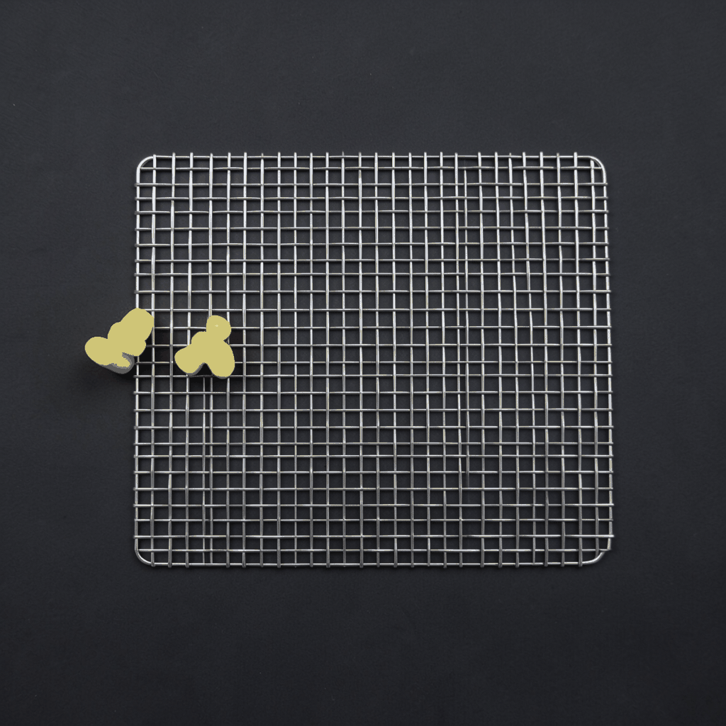
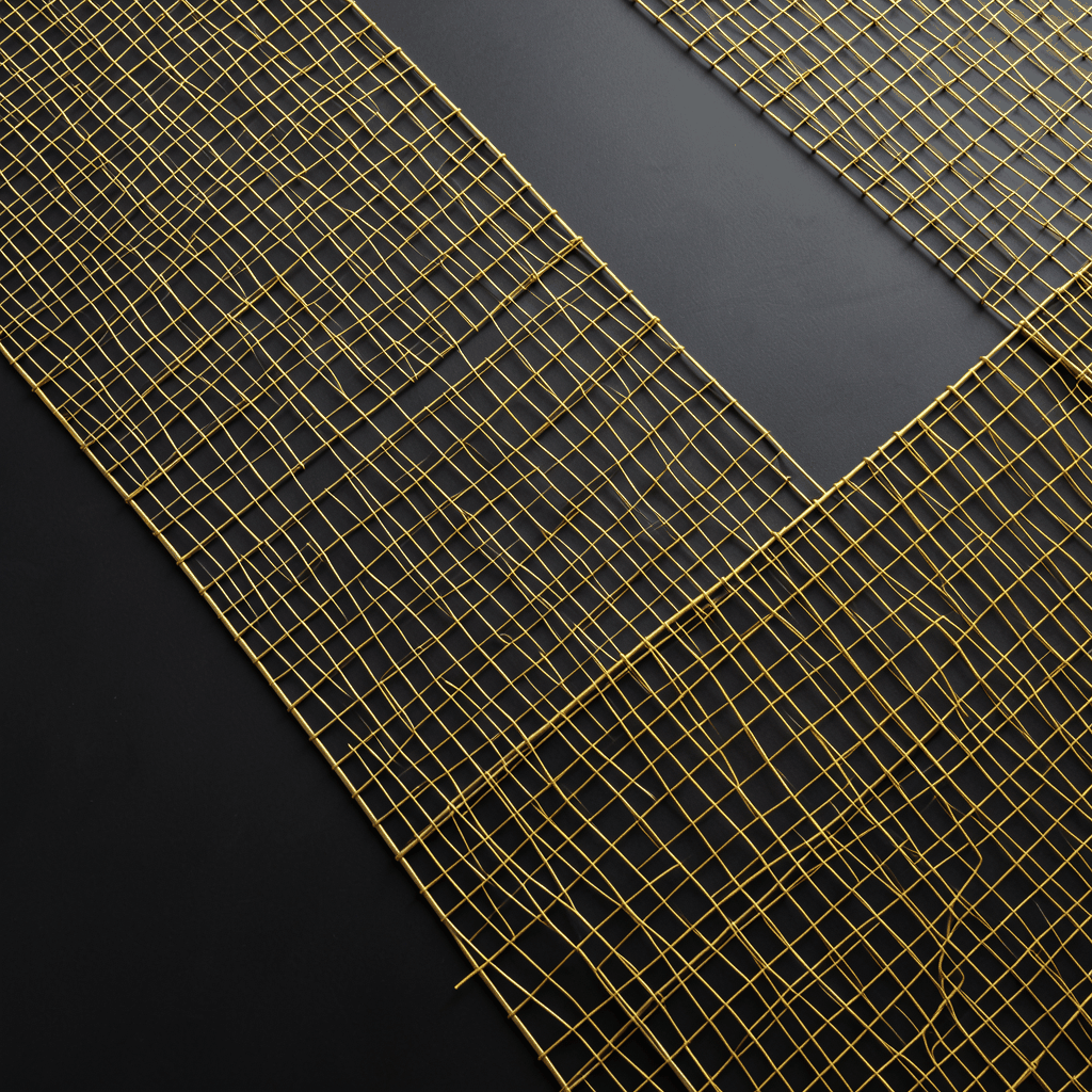
Tensioned wire mesh panels can give a curved building facade a lightweight, responsive appearance while providing solar screening, visual privacy, fall protection, or a distinctive architectural surface. The system can follow convex, concave, or irregular elevations, but successful installation depends on accurate geometry, suitable edge detailing, and controlled tension across every panel.
Unlike rigid cladding, architectural metal mesh responds to changes in span, temperature, and support alignment. A small error in the supporting frame can produce visible waves, uneven openings, or excessive stress at the fasteners. The installation process therefore begins long before the mesh reaches the site.
Stainless steel cable mesh, woven metal fabric, expanded metal, and other flexible or semi-flexible products may be suitable for curved applications. The correct selection depends on the facade radius, wind exposure, panel dimensions, required transparency, corrosion conditions, and the visual result specified by the architect.
Confirm The Facade Geometry
A reliable survey is the foundation of a curved wire mesh facade. Record the radius or changing curvature, panel boundaries, slab edges, parapets, columns, recesses, and any obstruction that could affect the support frame. Laser scanning or total-station measurements can help identify deviations between design drawings and the constructed building.
A facade may appear to have a consistent curve while actually changing radius between floors. In that situation, a standard rectangular panel layout can create gaps or localized tension. Divide the elevation into manageable zones and establish reference points for the top, bottom, and side edges of each panel.
The survey should also identify the substrate. Concrete, structural steel, aluminum framing, and masonry require different anchors and load-transfer details. Confirm the condition of the substrate, the position of reinforcement where relevant, and the allowable fixing locations before drilling or welding begins.
Panel geometry should include tolerances for fabrication and installation. Mesh should not be cut to the nominal opening alone. Allowance may be required for edge cables, rods, hems, turnbuckles, clamps, and the adjustment range needed to achieve consistent tension.
Select Mesh And Edge Components
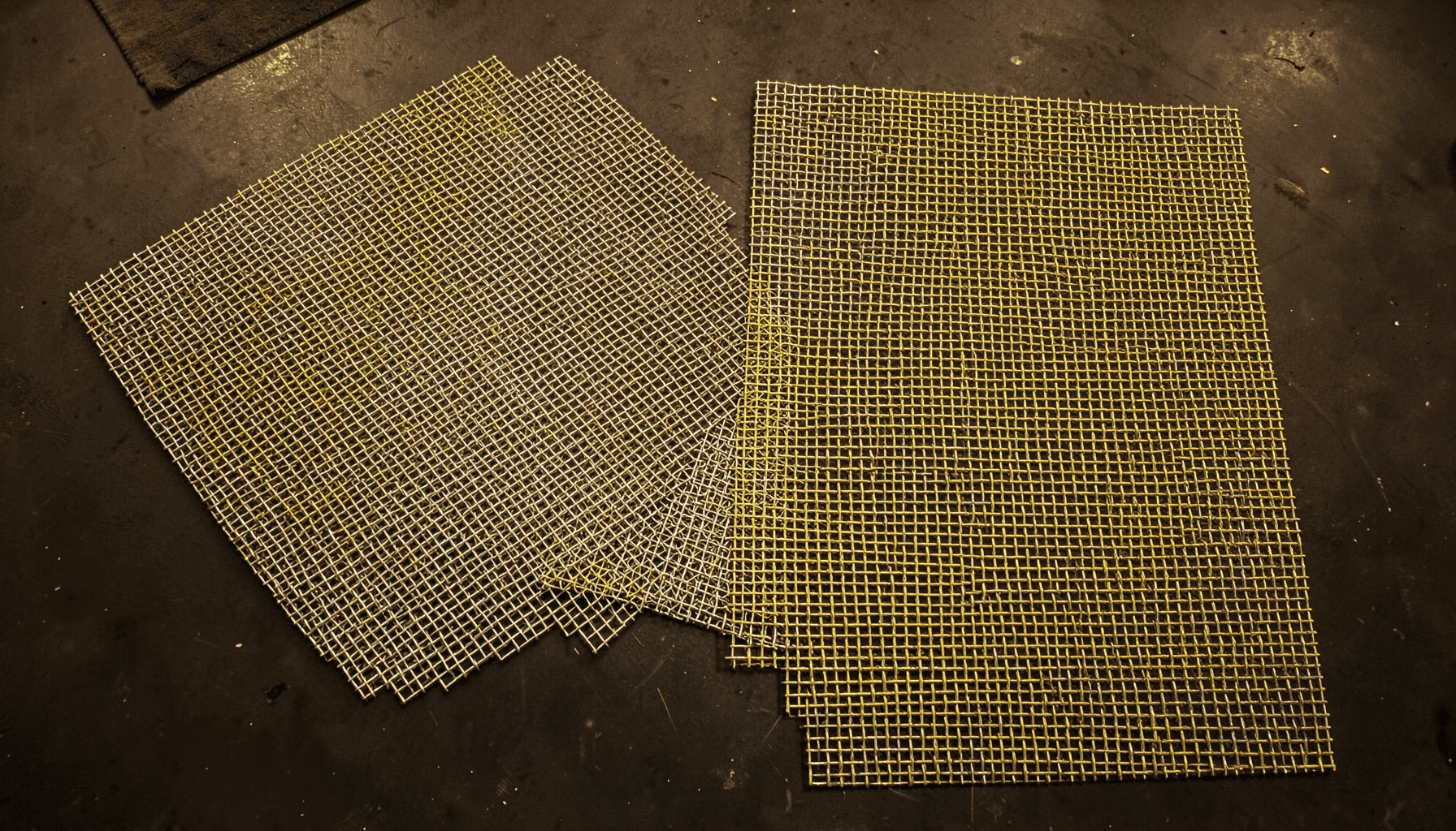
Stainless steel woven mesh is widely used for facade screening because it offers corrosion resistance, strength, and a clean architectural finish. Common grades include 304 for many inland environments and 316 or equivalent alloys for coastal, humid, or chemically exposed locations. Aluminum mesh can reduce dead load, while copper and specialty alloys may be selected for color or patination.
The mesh opening, wire diameter, weave, and percentage of open area influence both appearance and engineering performance. A dense mesh provides stronger screening and can reduce solar gain, but it also receives greater wind pressure. An open mesh is lighter and more transparent, yet it may need closer support spacing or stronger perimeter reinforcement.
Edge treatment is as important as the mesh itself. Typical options include reinforced selvedges, stainless steel perimeter cables, welded frames, flat bars, eyelets, lacing, or clamping strips. For large curved panels, a cable-supported edge with threaded terminals and turnbuckles provides useful adjustment. Framed cassettes may offer faster installation and more predictable alignment where the facade has repeating modules.
Specify fasteners, anchors, brackets, and tensioning hardware as one coordinated system. Mixing components with different corrosion resistance can create staining or galvanic problems. Stainless steel hardware should be isolated from incompatible metals when the environment and material combination require it.
Build A Support System That Follows The Curve
The supporting frame usually consists of horizontal and vertical rails, curved brackets, standoff arms, or a secondary steel structure fixed back to the building. Its role is to transfer wind and dead loads safely while maintaining the intended offset from the facade. It must also preserve a continuous line for the mesh edge.
For a regular cylindrical curve, curved rails can be fabricated to a calculated radius. For a changing or faceted facade, segmented rails may be more practical. Each segment should meet cleanly, with joints positioned so they do not create a visible kink or an abrupt change in panel tension.
Support brackets need sufficient adjustment in three directions. Horizontal adjustment helps align the panel along the curve; vertical adjustment controls the top and bottom edges; depth adjustment maintains a consistent stand-off from the wall. Slotted holes, shims, threaded rods, and adjustable clevises are commonly used for this purpose.
Before fitting the mesh, inspect the completed frame against the survey data. Check line, level, radius, bracket spacing, weld quality, coating condition, and drainage provisions. Any misalignment should be corrected at the frame stage. Pulling the mesh harder will not reliably compensate for a poorly aligned support structure.
Compare Panel Configurations
The best configuration depends on the facade shape, access conditions, panel size, and desired visual continuity. Smaller panels are easier to handle and replace, while larger panels reduce visible joints but require stronger lifting equipment and more precise tension control.
| Panel configuration | Suitable facade condition | Main advantages | Important limitations |
|---|---|---|---|
| Individual cable-edged panels | Regular curves and moderate spans | Easy adjustment, replacement, and tensioning | More visible joints and hardware |
| Framed mesh cassettes | Repeating bays or modular elevations | Fast installation and consistent edges | Higher weight and greater transport size |
| Continuous mesh bands | Long uninterrupted curved surfaces | Smooth visual flow with fewer seams | Difficult handling and more complex tension control |
| Segmented rigid frames | Faceted or changing-radius facades | Predictable geometry and strong edge definition | May show breaks between segments |
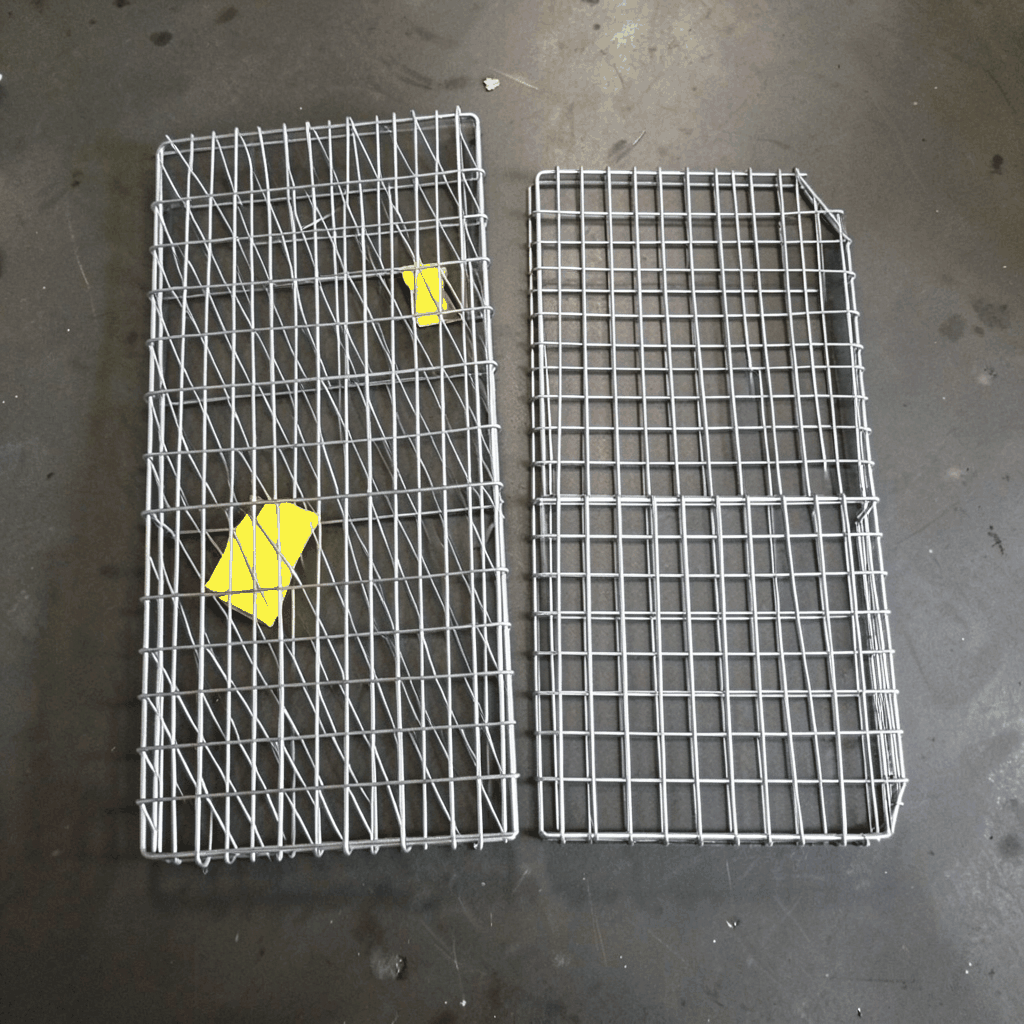
| Rod-reinforced mesh panels | Short to medium spans with defined boundaries | Clean perimeter and simple attachment | Less forgiving of substrate movement |
A mock-up is valuable when the mesh is highly visible or the building has a complex three-dimensional form. The sample should include the actual weave, edge finish, support brackets, fasteners, lighting conditions, and a representative section of the curve. Review it from ground level and from nearby occupied spaces.
Mock-up testing can reveal moiré patterns, unwanted reflections, excessive transparency, edge flutter, or inconsistent shadow lines. It also allows the project team to verify whether the chosen panel size can be safely moved through doors, around corners, and onto the installation platform.
Install And Tension The Panels
Installation should follow a controlled sequence established by the facade contractor and structural engineer. Set out the reference lines first, then install brackets and rails by zone. Where possible, begin at a stable corner, a central vertical line, or another clearly defined datum. Do not rely on the first panel to establish the entire facade geometry without checking it against the survey.
Attach one edge of the panel loosely, then connect the opposite edge and the remaining sides. For cable-edged panels, engage terminals, fork ends, clamps, or turnbuckles evenly. Avoid fully tightening one corner before the rest of the perimeter is connected, since this can pull the mesh out of plane or overload a local fixing.
Tension should be applied gradually and symmetrically. Work across opposite sides or in small increments around the perimeter, using the manufacturer’s recommended method. The aim is a stable, visually even surface rather than the maximum possible force. Excessive tension can distort the weave, damage edge cables, bend brackets, or transfer unintended loads to the building.
Curved surfaces deserve additional attention at panel corners and transitions. A panel that fits correctly at its center may form a gap near a changing-radius edge. Use adjustable hardware and planned overlap or closure details rather than forcing the mesh into position. Where the design uses overlapping panels, establish the overlap direction so water, light, and viewing angles remain consistent.
Control Wind, Movement, And Drainage
Wind loading is often the governing consideration for an external mesh screen. The open area of the fabric does not automatically eliminate wind load; pressure depends on mesh density, shape, building height, edge zones, turbulence, and the distance between the screen and the main wall. The support frame and anchors should be designed for the applicable local code and project-specific engineering criteria.
Large panels may require intermediate supports, especially on exposed elevations. These supports can reduce vibration and limit deflection, but they must be detailed so they do not create visible pressure points. Allow sufficient clearance from glazing, insulation, signage, louvers, and maintenance equipment.
Thermal expansion affects long facade runs and dissimilar materials. Provide movement capacity in rails, brackets, joints, and panel connections. Fixed points and sliding points should be defined rather than allowing random movement to accumulate at one end of the elevation.
Drainage and ventilation must remain open behind the mesh. Avoid creating pockets where water, dust, or cleaning residue can collect. Brackets should be shaped or positioned to shed water, and horizontal ledges should include suitable slopes or drainage openings. On coastal or industrial sites, detail the system so salt and contaminants can be rinsed away without trapping moisture against the building.
Inspect The Completed Facade
Quality control should take place at several stages, not only after the final panel is installed. Verify incoming mesh against the approved specification, including alloy, wire diameter, opening, finish, panel dimensions, and edge reinforcement. Inspect fasteners and tensioning hardware for damage, contamination, and correct material grade.
After installation, review the facade from multiple distances and angles. Look for consistent curvature, even tension, aligned joints, uniform openings, secure terminals, and adequate clearance from adjacent surfaces. Minor visual variation may be inherent to woven metal, but abrupt waves, slack zones, or twisted edges usually indicate a setup or support problem.
Record the final positions of turnbuckles, adjustable brackets, panel identification marks, and any approved deviations. This information helps future maintenance teams replace a damaged panel with the correct size and edge configuration. Keep product data, cleaning instructions, inspection records, and engineering calculations with the building maintenance documentation.
Routine inspections should focus on corrosion, loose fasteners, damaged wires, frayed cable edges, bracket movement, staining, and changes in panel tension. Cleaning methods must suit the alloy and finish. Harsh chemicals, abrasive pads, and contact with incompatible metals can permanently affect the surface.
Practical Recommendations For Project Teams
- Approve a full-scale curved facade mock-up before releasing repeated panel fabrication.
- Survey the installed substrate and secondary frame instead of relying only on architectural drawings.
- Specify mesh, edge reinforcement, fasteners, anchors, and isolation materials as one engineered package.
- Tension panels gradually with calibrated procedures and inspect the surface from several viewing distances.
- Include access, cleaning, replacement, drainage, and thermal movement in the original facade details.
Coordinate Fabrication And Installation
Curved facade mesh performs best when design, fabrication, structural engineering, and site installation are coordinated as a single process. Panel schedules should identify curvature, dimensions, edge details, hardware, finish, orientation, and installation sequence. Clear labeling reduces the risk of fitting a correctly made panel in the wrong location.
A manufacturer experienced in architectural and industrial metal mesh can assist with material selection, custom panel development, edge treatment, and production tolerances. Shuo Ke Wire Mesh Product Technology Co., Ltd. supplies customized stainless steel, aluminum, copper, iron, and alloy mesh solutions for architectural applications, including screening, partitions, cladding, fences, and other engineered metal products.
For a curved building facade, provide the supplier with elevation drawings, survey information, radius data, support spacing, wind criteria, finish requirements, and photographs of the substrate. Contact Shuo Ke to develop a coordinated mesh panel and support solution that can be fabricated accurately and installed with controlled tension on site.