How to Specify Wire Mesh for Electromagnetic Shielding Enclosures
Wire mesh can provide ventilation, visibility, acoustic openness, and electromagnetic protection in the same enclosure. It is commonly used for screened rooms, equipment cabinets, test chambers, medical equipment housings, industrial control systems, and communication infrastructure. The correct specification depends on much more than wire diameter or open area. Frequency, field type, enclosure geometry, joints, doors, and cable penetrations all influence the final shielding result.
A mesh panel may perform well in a laboratory sample and fail after installation if its edges are poorly bonded or if a large ventilation opening is left untreated. For this reason, electromagnetic shielding should be specified as a complete system rather than as an isolated material purchase. The mesh, frame, fasteners, gaskets, access panels, and penetrations must work together as a continuous conductive barrier.
Shuo Ke Wire Mesh Product Technology Co., Ltd. manufactures and processes metal mesh products in stainless steel, aluminum, copper, iron, and other alloys. These capabilities support customized solutions where shielding performance must be balanced with corrosion resistance, mechanical strength, appearance, airflow, and fabrication requirements.
Define The Shielding Objective
Begin with the electromagnetic environment rather than a preferred mesh style. Identify the equipment inside the enclosure, the likely interference sources outside it, and the frequencies that must be controlled. A requirement such as “EMI shielding” is too broad for procurement because a radio-frequency enclosure and a low-frequency magnetic shield require different construction methods.
Shielding effectiveness is normally expressed in decibels:
SE(dB) = 20 log₁₀(E₁/E₂)
The same concept can be applied to magnetic-field or power-density measurements. The required value should state whether it applies to electric fields, magnetic fields, plane waves, or conducted interference. It should also define the frequency range, test orientation, measurement distance, and acceptance criteria.
Near-field sources deserve special attention. At low frequencies and close distances, magnetic coupling can dominate, and a lightweight open mesh may provide limited protection. A copper or aluminum mesh can be highly effective against many radio-frequency electric fields, while low-frequency magnetic shielding may require high-permeability alloys, increased thickness, multiple layers, or a solid enclosure. The mesh specification should reflect the actual field conditions.
Choose Material And Mesh Construction
Material selection affects electrical conductivity, corrosion resistance, strength, weldability, appearance, and cost. Copper offers excellent conductivity and is often considered for high-performance electromagnetic shielding, but it can oxidize or react with dissimilar metals in humid environments. Aluminum is lightweight and conductive, making it suitable for removable panels and large structures. Stainless steel provides mechanical durability and corrosion resistance, although its conductivity is lower than that of copper or aluminum.
The alloy should be selected alongside the surrounding frame and fasteners. Contact between dissimilar metals can create galvanic corrosion, especially outdoors or in industrial environments. Where different materials are unavoidable, specify compatible finishes, isolation washers, conductive coatings, or protected joints. For architectural installations, surface appearance and color consistency may also be important, particularly when the enclosure forms part of a visible wall, partition, elevator area, or equipment room.
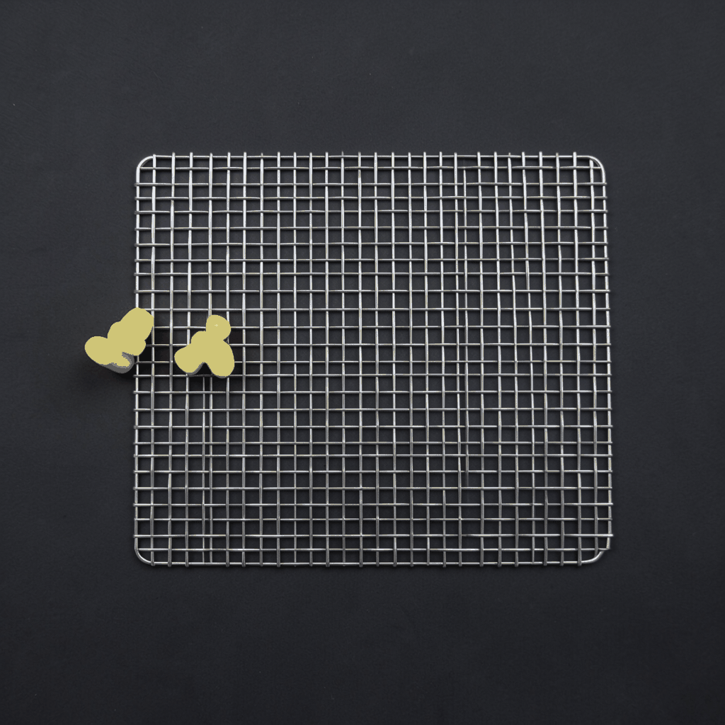
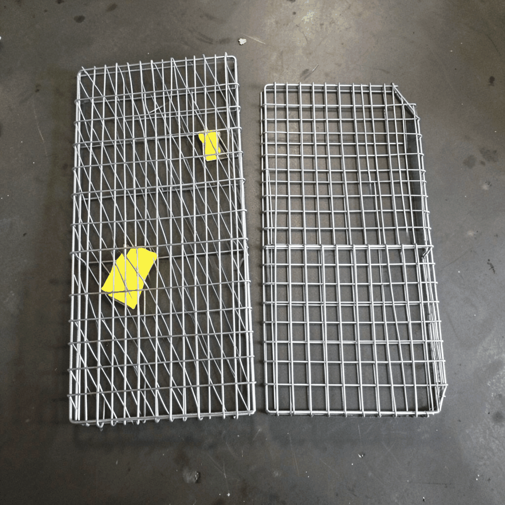
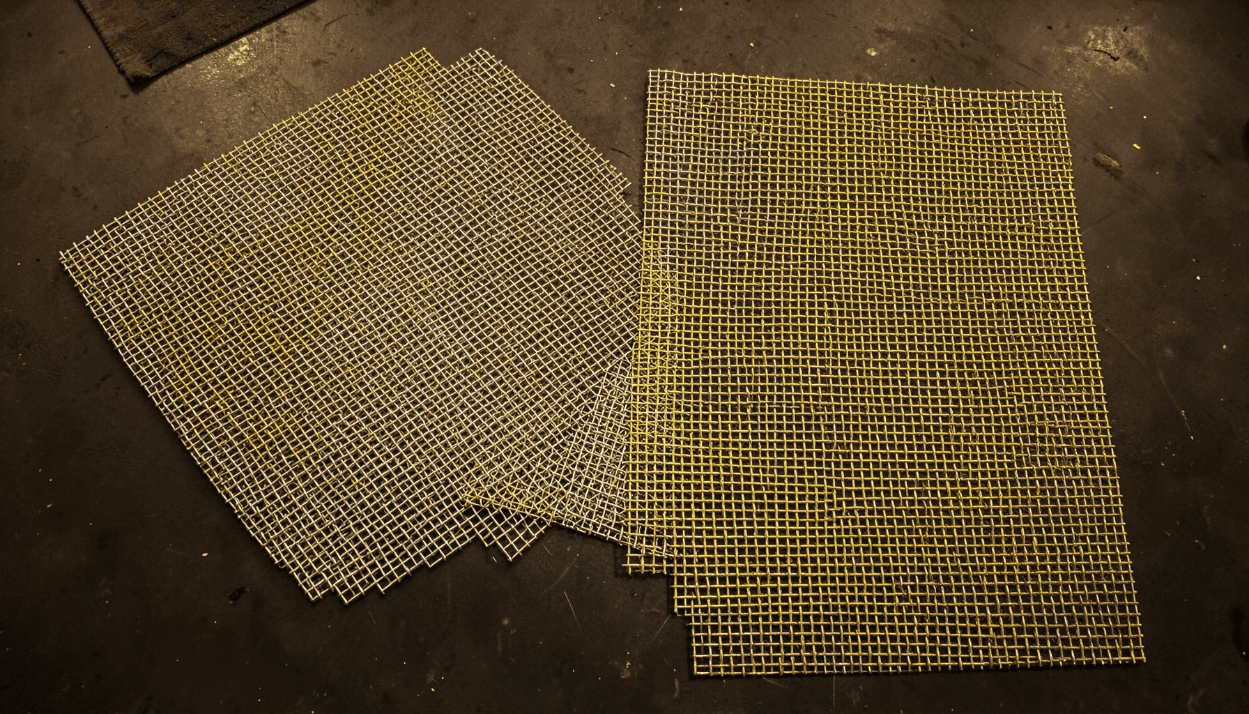
Wire diameter and mesh opening determine both mechanical behavior and electromagnetic performance. Woven wire mesh can be supplied in square, rectangular, or specialized patterns, while welded mesh may offer greater rigidity and easier panel fabrication. Expanded metal can provide a strong, economical screen, but its opening geometry and contact continuity must be evaluated for the target frequency. A fine, uniform mesh is generally easier to characterize than a decorative pattern with irregular openings.
Match Aperture Size To Frequency
Every opening acts as a potential leakage path. As frequency rises, the wavelength becomes shorter, so the same aperture becomes electrically larger. A commonly used preliminary rule is to keep the largest opening below approximately one-twentieth of the wavelength, although the appropriate ratio depends on the required shielding level, aperture shape, depth, and the number of openings.
The wavelength can be estimated using:
λ = c/f
where λ is wavelength, c is the speed of light, and f is frequency. For example, a 1 GHz signal has a wavelength of approximately 300 millimeters. A 15 millimeter opening is close to λ/20 at that frequency, but this calculation alone does not establish a guaranteed shielding rating. Multiple apertures can combine their leakage, and elongated slots often perform worse than compact openings of the same area.
Open area must be assessed together with wire thickness and mesh pitch. Ventilation screens may need a larger free area for cooling, while a test enclosure may accept a finer mesh to achieve greater attenuation. If airflow requirements conflict with shielding requirements, consider a deeper honeycomb vent, layered mesh, or a dedicated waveguide-below-cutoff ventilation panel. A qualified test program should validate the final arrangement.
| Design Variable | Effect On Shielding | Specification Consideration |
|---|---|---|
| Mesh opening | Larger openings generally increase electromagnetic leakage | State maximum clear aperture, not only nominal mesh count |
| Wire diameter | Affects electrical continuity, strength, and open area | Define tolerance and whether the measurement is before or after forming |
| Material | Influences conductivity, corrosion resistance, and magnetic response | Specify alloy or grade, finish, and compatibility with the frame |
| Mesh pattern | Controls aperture shape and panel rigidity | Identify woven, welded, expanded, or custom construction |
| Panel joint | Poor contact can create leakage around otherwise effective mesh | Require continuous conductive bonding or approved conductive gasketing |
| Frequency range | Determines the electrical size of each aperture | List minimum and maximum test frequencies |
| Cable and service openings | Can bypass the shielding surface | Use filtered connectors, conductive glands, or bonded waveguide penetrations |
Engineer Frames, Seams, And Penetrations
A mesh panel is only as effective as its perimeter connection. If the panel touches the frame at a few isolated fasteners, the interface may develop high contact impedance or small gaps. Specify a continuous conductive path using welded seams, a broad clamped contact, conductive gaskets, or closely spaced corrosion-protected fasteners. Paint, anodizing, powder coating, and dirt should not remain between surfaces that must conduct unless a tested conductive finish is provided.
Doors and removable covers require particular care. Compression gaskets made with conductive elastomers, knitted wire mesh, or beryllium copper fingers can maintain contact when the enclosure is opened and closed. The gasket should be compressed evenly around the entire perimeter. Hinges, latches, handles, and reinforcement members must preserve the conductive path rather than interrupt it.
Cable entries, ventilation openings, power connections, and optical access points are common sources of shielding failure. Specify filtered connectors, conductive cable glands, shield termination hardware, or bonded penetration panels as appropriate. Avoid long unbonded pigtails for cable shields because they can increase inductive impedance at higher frequencies. Each penetration should be treated as part of the electromagnetic design, not as a later installation detail.
Verify Performance With A Defined Test
A procurement specification should separate material properties from finished-enclosure performance. A mesh manufacturer may provide alloy certificates, wire diameter, mesh count, aperture dimensions, tensile information, and surface-finish data. These documents confirm that the material matches the order, but they do not automatically prove the shielding effectiveness of the assembled enclosure.
The verification method should be selected according to the application. Shielding effectiveness tests may use standardized reverberation, insertion-loss, or enclosure methods, depending on enclosure size and frequency range. Large screened rooms may require site testing after installation, while small cabinets can often be tested in a laboratory fixture. The test report should record equipment configuration, antenna position, polarization, frequency sweep, door condition, cable arrangement, and environmental conditions.
Ask for samples when the mesh is custom, decorative, formed, or integrated with a special frame. A representative sample should include the actual mesh, edge treatment, fasteners, gasket, coating, and joint design. Testing a loose piece of mesh cannot reveal leakage through seams or penetrations. For critical installations, a prototype enclosure or full-size panel mock-up provides more useful evidence before production begins.
Coordinate Fabrication And Installation
Mesh intended for shielding should be designed for manufacture from the beginning. Forming, cutting, welding, brazing, and trimming can change aperture dimensions or damage the conductive surface. Drawings should identify finished panel size, flatness, bend radii, frame details, joint locations, hole tolerances, and areas that must remain free of nonconductive coatings.
Architectural and industrial projects often require the shielding screen to perform additional functions. Stainless steel may be selected for a public-facing partition because it resists wear and supports a clean decorative finish. Aluminum can reduce the weight of a large access panel. Copper mesh may be selected for a specialized cabinet where conductivity is prioritized. The practical choice depends on the environment, handling method, cleaning chemicals, temperature, and expected service life.
Installation instructions should define how the enclosure is bonded to the building ground or equipment ground where required by the electrical safety design. Grounding and electromagnetic shielding are related but separate functions: a grounded enclosure may still leak through poor joints, while a well-bonded mesh may require a separately engineered protective-earth connection. Coordination among the mesh processor, electrical engineer, enclosure builder, and installer prevents late modifications that compromise performance.
Prepare A Complete Purchasing Specification
A clear request for quotation allows manufacturers to recommend a suitable construction instead of pricing an ambiguous mesh description. Include the operating environment, performance target, and fabrication requirements together. The following items are useful when preparing drawings and purchase documents:
- State the required shielding effectiveness in dB, the field type, and the complete frequency range.
- Define maximum aperture, wire diameter, mesh pattern, material grade, finish, and dimensional tolerances.
- Show frames, seams, doors, removable panels, fasteners, gaskets, cable entries, and ventilation paths.
- Identify corrosion, temperature, cleaning, fire, mechanical-load, and appearance requirements.
- Specify prototype approval, inspection documents, test procedures, and acceptance criteria for the finished assembly.
A manufacturer with mesh processing and custom fabrication experience can review these details for manufacturability. Shuo Ke Wire Mesh Product Technology Co., Ltd. can support material selection, cut-to-size processing, formed components, architectural finishes, and customized metal mesh solutions for industrial or commercial enclosures. Sharing frequency data and enclosure drawings early helps align shielding, durability, airflow, and visual requirements before production.
Send the required frequency range, target shielding level, mesh dimensions, material preference, frame concept, and penetration details with your project inquiry. Shuo Ke can then evaluate the design and develop a practical wire mesh component or complete customized shielding solution suited to the application.